
Please, check our SMD/THT services - smd.lotharek.pl; from idea to ready devices
Please, check our SMD/THT services - smd.lotharek.pl; from idea to ready devices
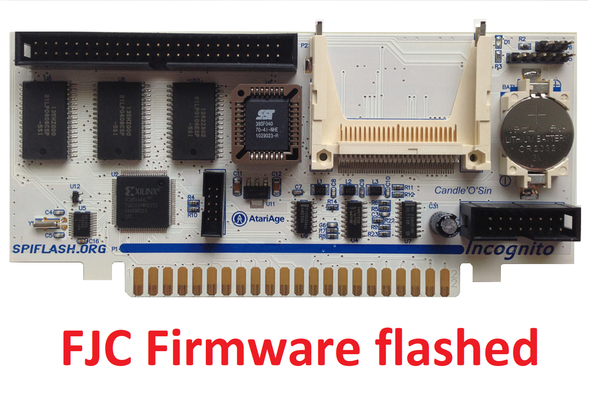
INCOGNITO 1MB FLASHED WITH FIRMWARE byj FJC ;
commision is paid to creator of hardware and FJC / firmware/ from every unit sold and warranty kept
VISIT FJC`s PAGE to read about diffrences :
https://atari8.co.uk/firmware/incognito/
Feature list:
.jpg)
Disclaimer:
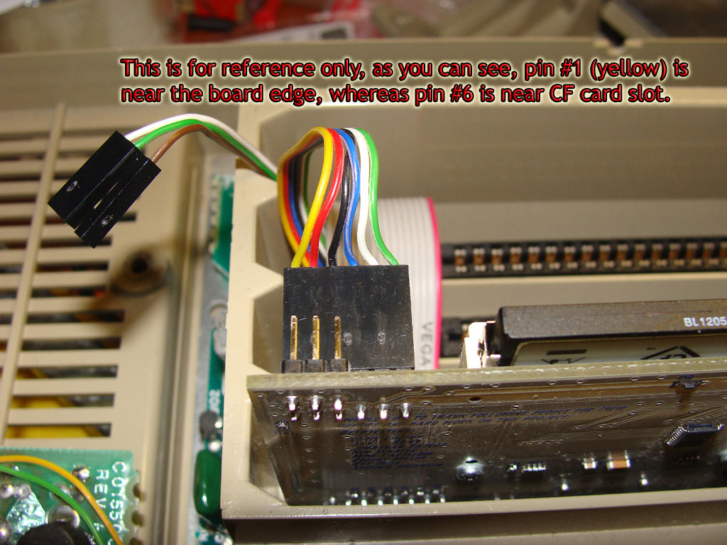
ALL MENTIONED COLOURS OF WIRE ARE FOR REFERENCY ONLY ! DO NOT FOCUS ON COLOURS
Installation manual:
Opening your 800
This is quite easy. All you need to do is remove trap-door, all the expansion card that you have inside (this includes all three RAM carts plus Personality/ROM board. After this, you"ll have to turn the unit upside-down, and unscrew 5 screws in the corners, and in the middle of front edge. Now you"re able to open the case - lift top of the enclosure just enough to get a hold on keyboard ribbon - disconnect it from the backplane - please take a closer look on how it is connected - ribbon has plug wider than the connector on backplane (motherboard) and you"ll have to connect it back just the way it was when reassembling the unit.Now, since you have clear view of power board and aluminium casting covering most of the backplane, disconnect the internal speaker and remove whole casting with all what is connected to it from the case.You"ll find loads of screws to be removed on bottom side of the cast holding an aluminium plate to the top part. After this, disconnect 4 pin header leading from backplane to power board, and try to separate the casting from backplane - it will come off with power board, but this is the way it should be.Now the aluminium plate - it holds to the PCB by 4 expansion plugs - they are made from two parts - one is a pin that was inserted in the collar that expanded and made connection permanent, you need to use small flat-headed screwdriver to push it all the way out, so you"ll be able to remove the collar.What you should have now, is the backplane PCB together with CPU board and plastic part that forms cartridge slot covers and expansion cards compartment. To get rid of it you"ll have to gently pry and push four snap-ins you find accesible on the bottom of backplane PCB.Since you already have all that was required separate, you may proceed with installation.
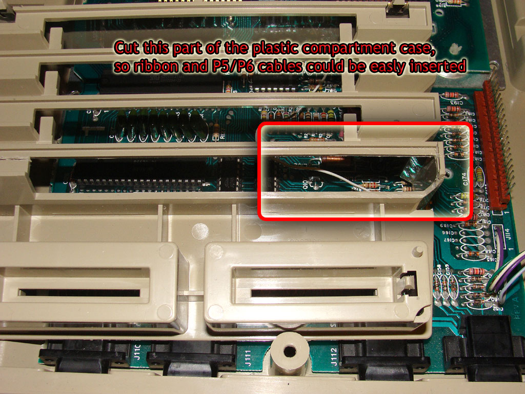
Readjusting the cutout
It is nice to have Personality slot opening a bit wider than it is originally, so you can pass ribbon cable and auxilary connectors cables freely. Please see the picture for the details. Some might think it not the best idea, but this way nothing gets compressed as it will be reassembled and the chances of getting something short-circuit are almost nil.
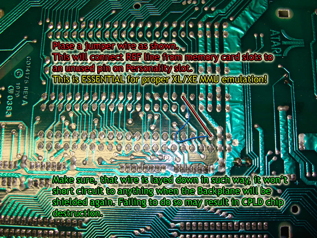
Jumper wires
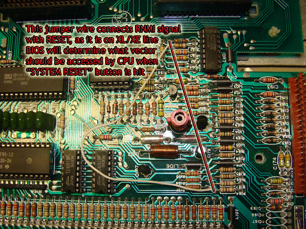
You"ll have to make two jumper connections on your board (see the pictures) - one connects REF signal from memory slots to the not used pin on personality slot - and this is essential for emulated MMU chip on Incognito boardThe ohter is a jumper between RNMI and COLD-RESET pins, so that CPU would be in known state when the board is re-initialised. Remember than 400/800 had no real RESET, instead it had Request NMI line (sometimes reffered as to RESET NMI) that did some kind of software reset - as this was OK for 400/800 system, when ROM was connected to the system bus permanently, it"s not acceptable for XL/XE when you can disconnect ROM by writting to PORTB. BIOS will handle RESET vector and redirect CPU to the valid location instead.
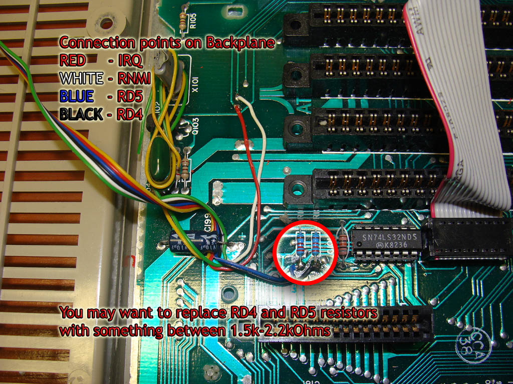
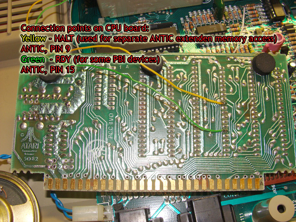
Making connections for auxiliary header P5This is essential for true XL/XE compatibility, as there are signals you need to tap in that are not present anywhere else in the system. These are:
Please see the picture for tapping points for all these signals.Additionaly, you may want to replace RD4/RD5 pulldown resistors to something ranging from 1.5k to 2.2kOhms. It will improove compatibility with cartridges, as protection resistors on Incognito board form with original ones voltage divider that may render some carts unusable.
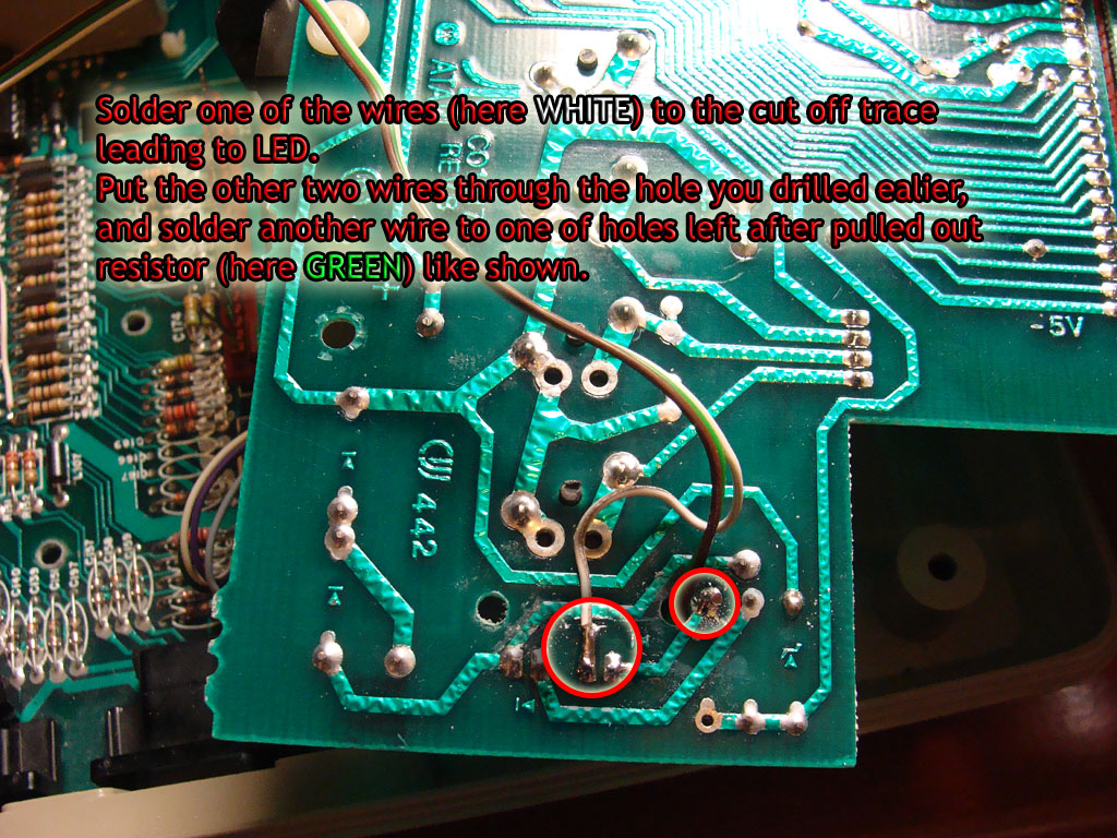
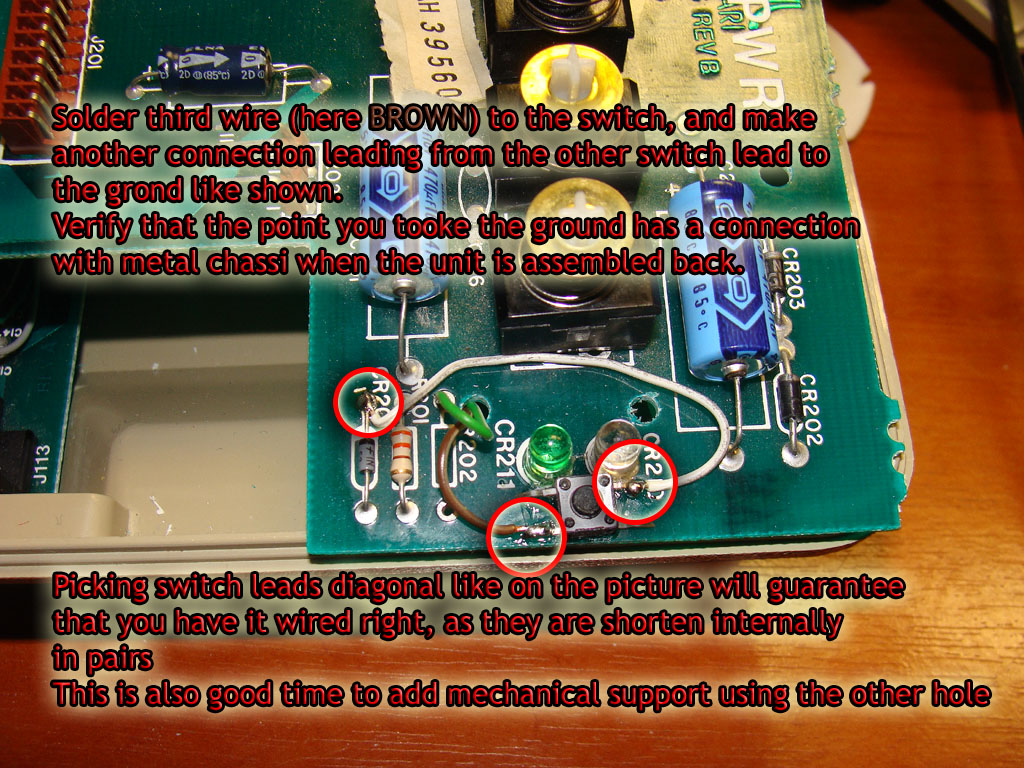
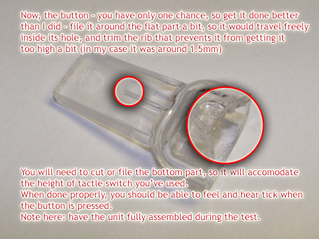
ATR change button, HDD activity LED, connector P6
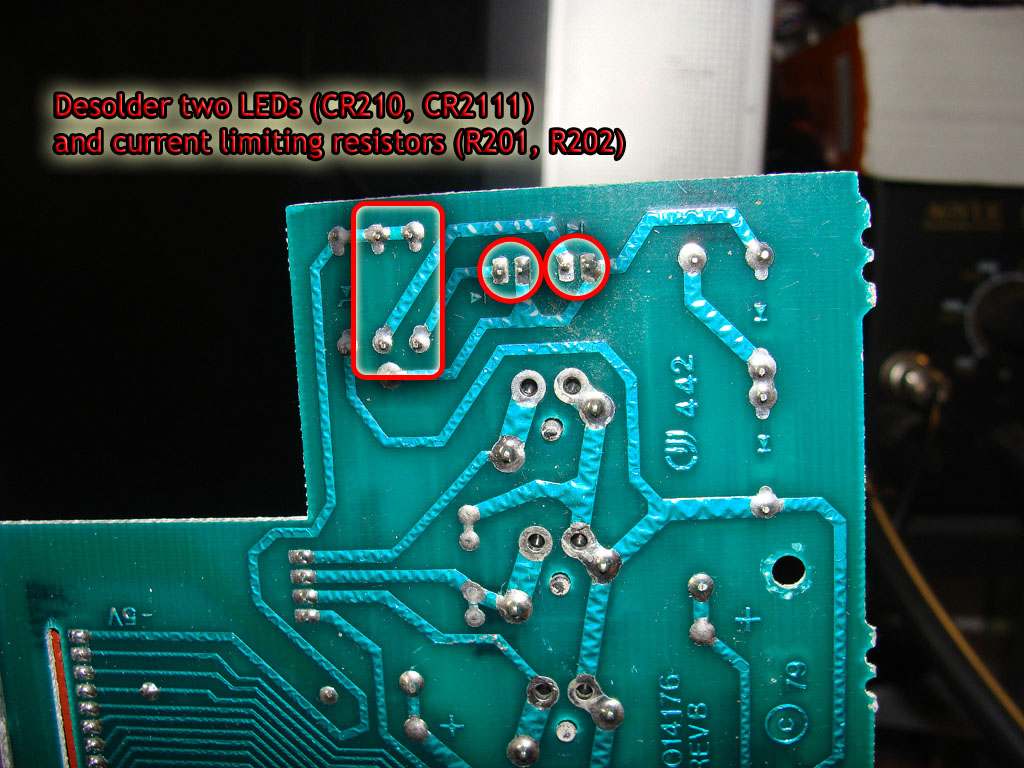
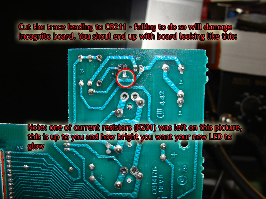
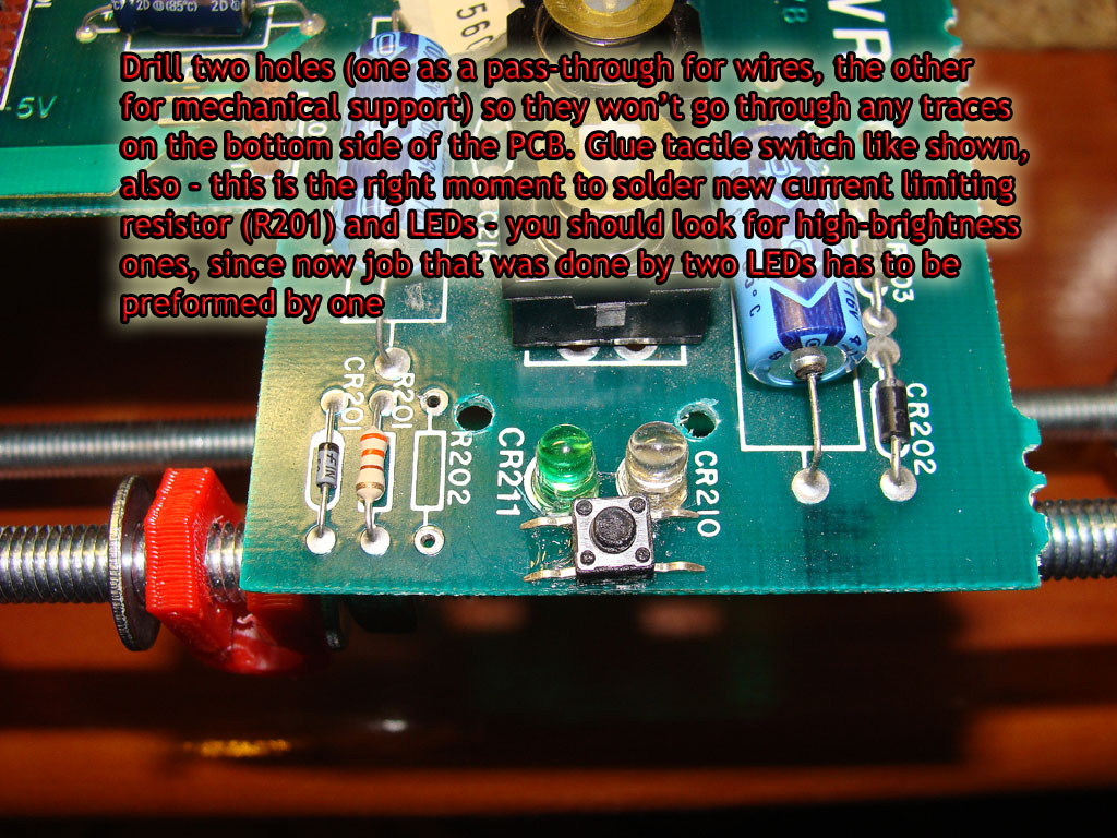
If you want to use these features, you"ll have to make some readjustments to power board - this way you won"t have to drill any ugly holes in your 800 case, instead it will be as discreet as it can be - after this, your light conductor just under START button becomes another button, just for cycling mounted ATR files, and it still serves it purpose as power indicator plus hard disk activity indicator.P6 pinout goes as follows:
To accomplish this, follow the pictures.
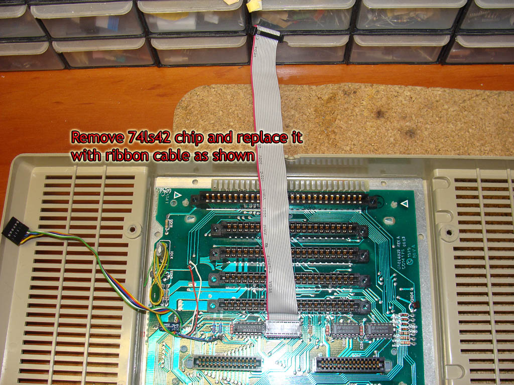
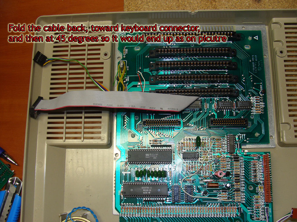
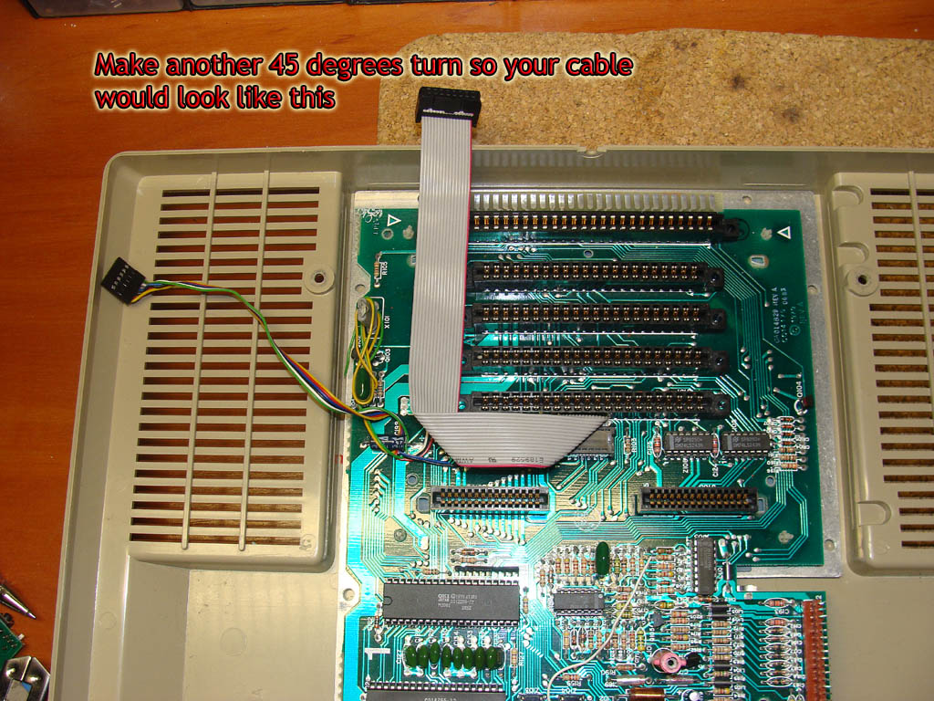
Replacing 74LS42 with ribbon cable
You need to remove 74LS42 chip (location Z101) and replace it with ribbon cable that was included in the kit. Fold the cable as shown.
Putting everything back together
Now you should have everything prepared for the Incognito board, all you have to do is to reassemble your unit.Start with taking the ribbon and the P5 and P6 header cables through the opening you cut in the plastic part of expansion boards compartment. When you done, put the compartment back in its place - it should snap back in and stay firmly attached to the PCB.Now proceed with the aluminium plate. Align it so holes in PCB match holes in the plate, and then put the expandable collars in those holes. When you put first one take that pin you"ve taken out of it, and put it back - this wil fix the plate and easier the align of remaning holes.When completed you should reassemble the casting with the backplane PCB - just don"t start screwing it tight again, as it will be better if you check everything up before you do that.Install the Incognito board in first slot (the one that was occupied by ROM board) and turn the unit on - Incognito BIOS screen should show up. If it doesn"t - recheck all your connections, especially those two jumper wires and RD4/RD5/RNMI lines.Please make sure you didn"t short circuit anything during the reassembly, as shorting any xilinx pin directly to the one of power rails (5V -5V or 12V) will kill it instantly